

Stacking Cradles
Time saving as an advantage
By using a TRUNINGER magnet system you save not only space, but lots of time as well.
Magnets, when properly operated, allow you to:
- Approach the load quickly and reliably
- Grip the load securely
- Lift the load from its storage location in a few seconds
Magnet systems also enable everything in the warehouse to be tightly packed, which results in shorter average crane travel distances and therefore saved time.
Handling more material in a small space
Where automatic storage of long products is not economical, storing material in stacking cradles can be a useful alternative. In situations where small volumes or small quantities of material are stored and transported, what is needed is often just a lifting system which allows:
- Easy access
- Low space requirement
- Simple operation
Using a stacking cradle system it is possible to store large quantities of material in a very compact space. Such a storage system is the ideal, flexible solution for space-saving, safe storage of long and/or flat material as well as products in large quantities.
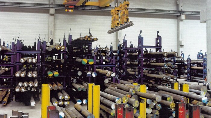
Figure 1: View of a typical stacking cradle storage system
Magnet system with cradle carriers
Cradle carriers fixed on the magnet beam allow several operations with the same system:
- Rapid loading of the bundle into the stacking cradle
- Simple mechanical re-stacking of cradles
- Precise order picking of individual items using the magnets
By using the cradle carrier system to alter the stacking order, material lower down is always accessible. There is no longer any need for any manual rearranging.
The magnet system’s cradle carriers are located between the two magnets of a magnet group. The lugs are swivelled out by a motor.
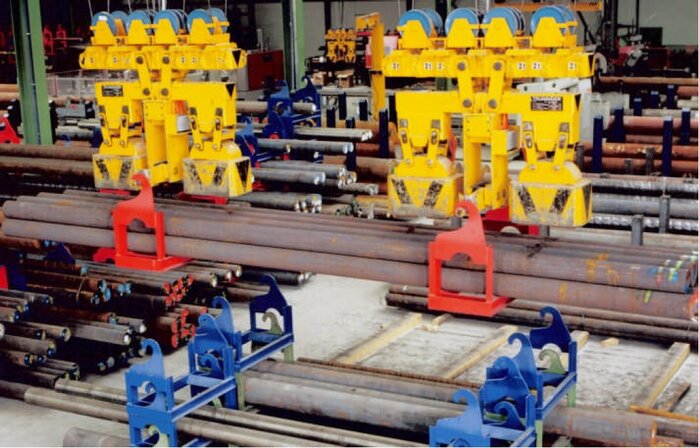
Figure 2: Mechanical restacking of a cradle
Before order picking with the magnets the motor swivels the lugs back. The entire cradle carrier is no wider than the magnets. Long material can therefore be picked without any obstruction.
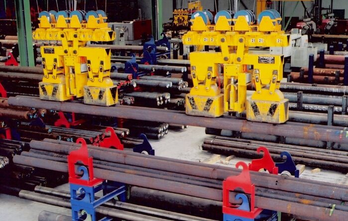
Figure 3: Order picking from the stacking cradle
For structural reasons a different cradle carrier design is needed for wide or flat loads. Here the carrier lugs no longer get swivelled out. Instead a motor rotates the entire carrier mechanism.
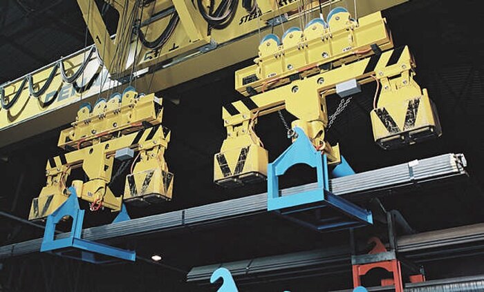
Figure 4: Carrying cradles using rotatable carrier mechanisms
Your benefits at one glance
|
|
Slewing magnets
Flexibility and safety
Flexible movement makes it possible for the magnet spreader beam to be adapted to users’ varying requirements. Magnet slewing plays a central role in this.
Slewing magnets are used not only because of their great adaptability, but also because they play an important part in magnet systems’ ability to handle materials safely.
The magnets are slewed, either manually or by motor drive, before they are set down on the load. Slewing magnets are extremely useful in the following situations:
Many different materials—one magnet system
It is often necessary to lift various loads of differing dimensions using one and the same magnet system. A typical such application would be handling steel bars and sheet metal in the same bay of a warehouse. The magnet spreader beam needs a high degree of versatility to adapt to the various dimensions and different materials.
For steel bars the magnets are positioned parallel to the load, while for carrying sheet metal they are slewed 90 degrees.
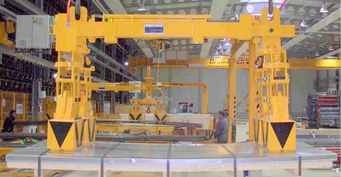
Figure 1: Magnets slewed 90° on a pack of sheet metal
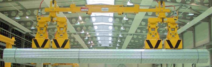
Figure 2: Magnets turned parallel to the load, lifting a bundle of pipes
Varying material widths – high-density storage
A profitable warehouse succeeds when offering a good range and mix of products. Consequently material of different shapes, lengths and widths are found in the storage area and each of them makes different use of the space. The warehouse will yield higher returns when all products are stored as compactly as possible and when the product mix does not consume too much space.
Slewing magnets help to increase storage density by adapting to the width of each material. For narrow loads or individual bundles the magnets are placed parallel to the load. For wide loads or for lifting more than one bundle at a time the magnets are slewed.
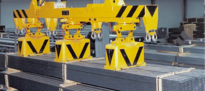
Figure 3: Slewing magnets lifting three bundles of pipes simultaneously
Safety when lifting wide loads
The magnets used for beams or sections are very slim, allowing to pick single beams even in narrow gaps. Spaces between material stacks and between aisles are deliberately avoided in order to reduce cost.
In a warehouse for beams or sections the material is stored in many different sizes. I-beams of both 100 and 1,000mm in width may be found. For wide beams, setting the magnets down in the middle is difficult to achieve. Positioning the magnets at an angle prevents the load from tilting about the long axis when picked off-centre.
Slewing magnets are thus a basic requirement for transporting the load safely!
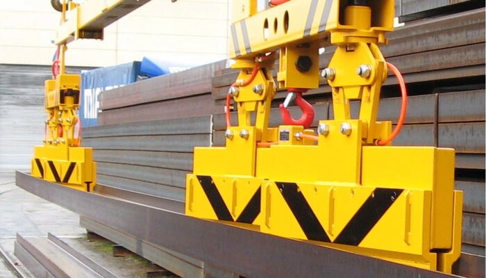
Figure 4: Slewing magnets placed at a slight angle on a wide load
Load temperature > 120°C
Example: Hot billet handling up to 600°C
Thanks to the transport of hot material, sequential processes in the steel mill can run at “the same temperature”. This means, that material does not need to be heated up again for further processing, thus saving considerable time and energy.
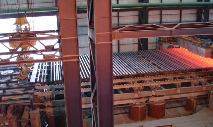
Figure 1: TRUNINGER magnet system for loads of temperatures of up to 600°C
General Considerations for Handling Hot Loads
For magnetic handling of hot loads a number of physical properties and design issues need to be considered:
- Steel loses all of its ferromagnetic properties at temperatures above 768°C.
- Hot metal products are not as stiff as cold products. The increased flexibility of the product results in more deflection. This increased deflection needs to be carefully considered in the design of a suitable magnet handling system.
- At load temperatures of 600°C, the lifting force of the magnet is significantly reduced compared to the force generated by an equivalent magnet at 0°C.
- Special precautions must be taken to protect the magnet electrical system from the heat.
- The design of any magnet spreader assemblies needs to be as simple as possible. Active (motorised) spreaders require drive assemblies which in most cases are not capable of withstanding constant exposure to high temperatures. Lubrication of moving parts is also more difficult due to the generally lower melting point of lubricants used for moving parts.
- Devices such as proximity switches or sensors are also generally unreliable when constantly exposed to high temperatures. Sensors must be either removed or protected against the heat.
TRUNINGER “HOT” Magnets
Our long term experience as a manufacturer of magnet systems allows us to offer a wide range of magnet lifting solutions for hot load handling. Thanks to the following features, hot loads at temperatures of up to 600 °C can be transported safely:
- High temperature resistant sealing compound
- High temperature resistant insulation material
- Reflective plates to protect the magnet coil from radiated heat
- Thermal insulation layers within the magnet to separate the magnet coil from the heat
- Magnet housing designed for passive cooling
- Heat resistant power supply cables with additional heat protection device
Slewing Device
Compact but rugged
There are a number of reasons why it may be necessary to rotate a load:
- To achieve optimum alignment on a truck, train or ship
- To get high storage density in a warehouse
- To handle different alignment of material in the stock reception area and on the production line
- To scan loads for automatic identification devices (e.g. barcode readers) in the stock reception area
- A motorised load slewing device allows the load to be rotated by remote control
Rotating a load during transport can be done in two ways:
- By a slewing crab on the crane
- By a slewing device on the spreader beam or on the magnet itself
Note:
Slewing devices often add significantly to the cost of magnet systems or cranes. If you have the option to plan your storage layout, it is therefore very advisable to consider a fix alignment of material, machines (processes) and loading or unloading. This will not only safe investment costs but also cycle time.
Decision criteria for slewing crabs on cranes
Cranes with a slewing crab replace the corresponding device on the side of the magnet system. This leads to lower weights of the magnet system and consequently to a relief or smaller dimensioning of the crane hoist.
A slewing crab can also make sense for very long loads for static reasons and to minimize the weight of the load handling attachment.
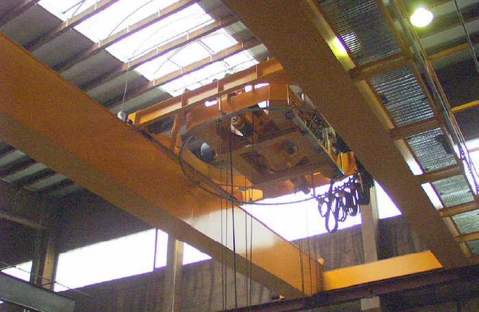
Figure 1: Slewing crab on a crane
Slewing device on magnet system
A load slewing device on the spreader beam or on the magnet itself makes sense when the footprint of such device does not collide with narrow gaps in the store area. It often provides the only option when retrofitting an existing crane with a new magnet system.
Another advantage of having a load slewing device on the magnet beam is the better visibility to an operator located on the ground. It also offers a higher quality of control to the crane driver. Slewing done from the crane is less precise due to the rotation being transmitted to the load via steel ropes, a setup which is prone to rotational swaying.
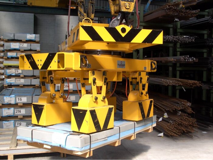
Figure 2: Magnet spreader beam with load slewing device
Load slewing on magnet
For special applications, it is even possible to place a load slewing device on a single magnet. Load slewing devices are often used with coil magnets; this allows coils to be turned remotely.
Power can be supplied to the magnet within the load rotating mechanism by means of slip rings, if required. This avoids a limitation of the rotation range.
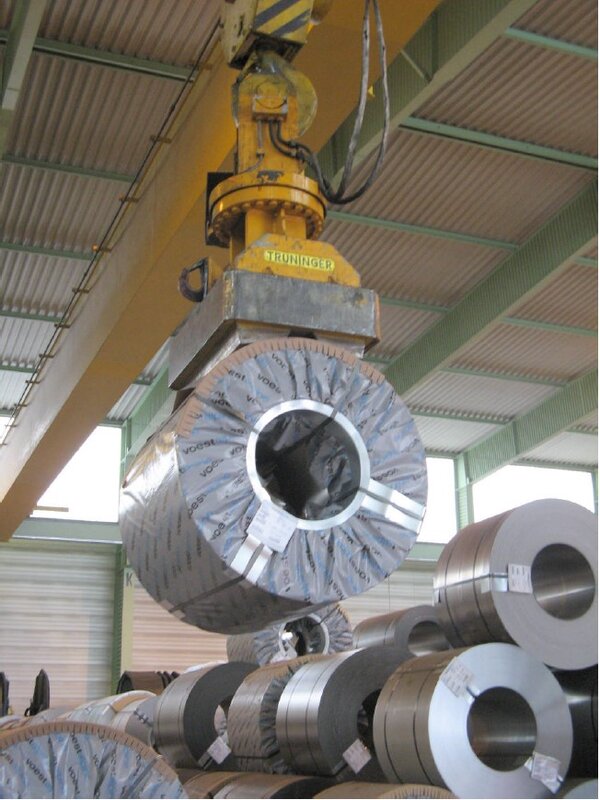
Figure 3: Load slewing device in combination with a coil magnet
QuickChange™ System
Flexibility increases profitability
The QuickChange™ system enables a single crane to use a range of different magnet spreader beams.
The lower spreader beams are remotely coupled with the permanently installed upper spreader beam, and the mechanical and electrical connection is made automatically.
For moving the individual sections from the warehouse to the saw, to the sandblaster, to the processing centre or to the dispatch area, especially narrow magnets are used, enabling the cranes to work even in tall narrow aisles between the stored material. This keeps the system usable even at maximum storage density.
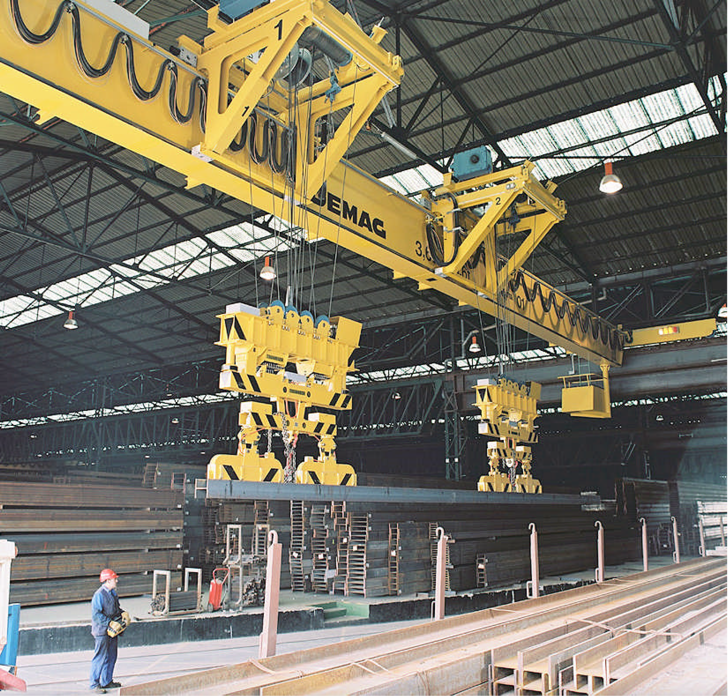
Figure 1: QuickChange™ system with lower spreader beams for handling individual sections
Switching spreader beams faster and with added ease
The sections are usually delivered by train or ship in packs weighing up to 8,000kg. To keep costs down, these packs of sections need to be unloaded and moved to their respective storage locations as quickly as possible.
Large magnets with a deep magnetic field are used to move the packs around efficiently and safely.
These magnets are attached to two further lower spreader beams. To change magnets, first the two lower spreader beams for individual sections are lowered onto their spreader beam stands and decoupled.
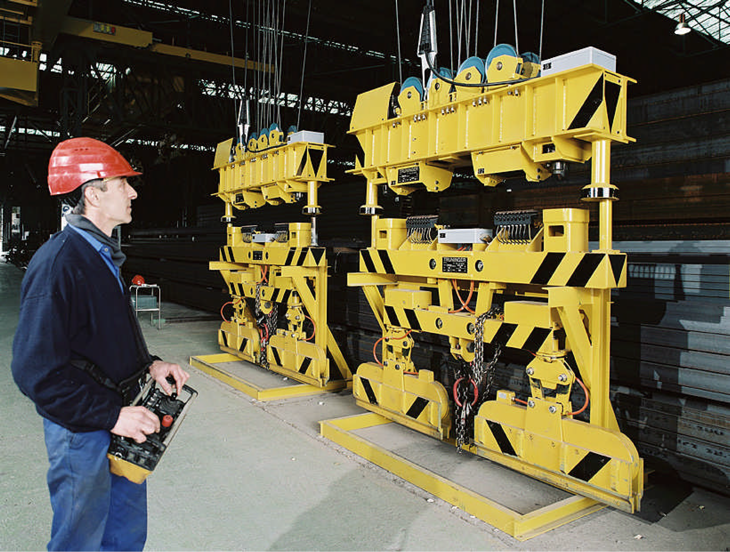
Figure 2: Automatic decoupling of the lower spreader beams for individual sections
Then the two lower spreader beams for girder bundles are picked up. The crane operator changes the crossheads at the push of a button within a few seconds, without having to release or connect hooks or plugs.
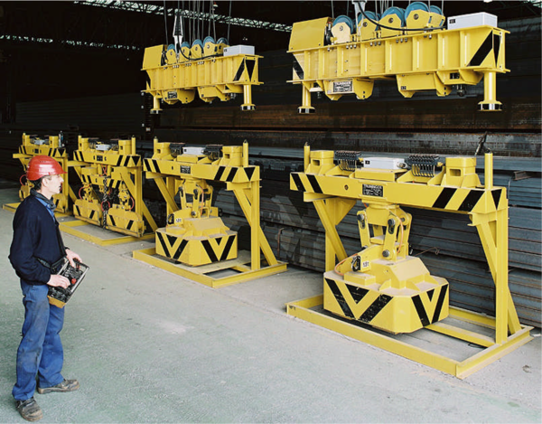
Figure 3: Quick coupling up of the section pack magnets for fast and efficient unloading of trains and ships
Systems against residual magnetism
Fast gripping and safe material transport to the warehouse
Why demagnetisation of the load can be critical
In material handling applications where the steel has to pass though automated processing lines, residual magnetism in the load can cause serious problems. The load may ‘stick’ to machine parts as it travels through the production line or it may attract other small pieces of steel (washers, bolts, swarf etc).
In these situations efficient demagnetisation of the load is essential. SmartPick offers configurable demagnetisation for eliminating a maximum amount of residual magnetism in minimum time.
What happens when steel becomes magnetised?
Ferromagnetic materials such as such as mild or quality steel which have never been subjected to a magnetic field are made up of randomly ordered magnetic ions as represented below in Figure 1. Steel, when in this state, has no magnetic effect on its surroundings (see point a in Figure 3).
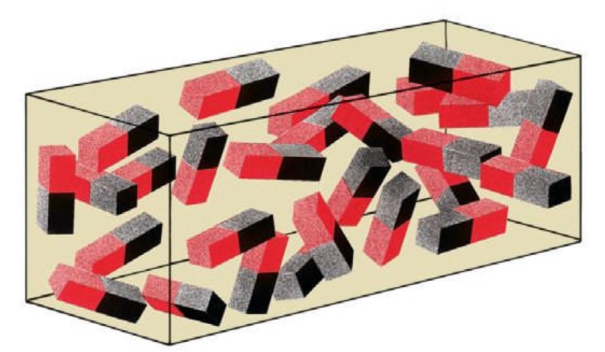
Figure 1: Ions positioned at random (material demagnetised)
When a positive magnetic field is applied, the magnetic ions start to fall into alignment. The more powerful the magnetic field, the more tightly the ions are aligned. If all of the ions are aligned as shown in Figure 2:, the material is said to be magnetically saturated (Point b in Figure 3:). For steel the magnetic saturation is equal to 2.4 Tesla.
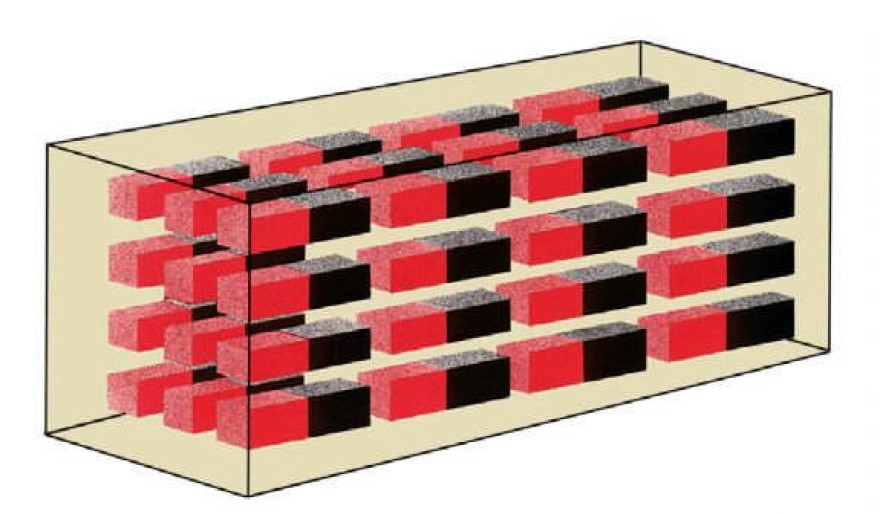
Figure 2: All ions aligned (material magnetically saturated)
However, when the external magnetic field is removed, the ions do not return to their random state. This leaves some residual magnetism in the material, an effect known as remanence (Point c in Figure 3).
This residual magnetism has to be removed by some external means. The actual method applied depends mainly on the magnetic properties of the material. Material such as mild steel loses its magnetism quickly and is said to be ’soft magnetic’. Quality steel on the other hand, loses its magnetism very slowly and is therefore said to be ‘hard magnetic’.
RDS (Reverse Degauss System)
RDS demagnetisation eliminates residual magnetism from mild steel. Applying a negative magnetic field causes the magnetic ions to gradually adopt a random alignment. When the opposing field is turned off (Point d in Figure 3:), the ions are randomly aligned, thus eliminating the residual magnetism.
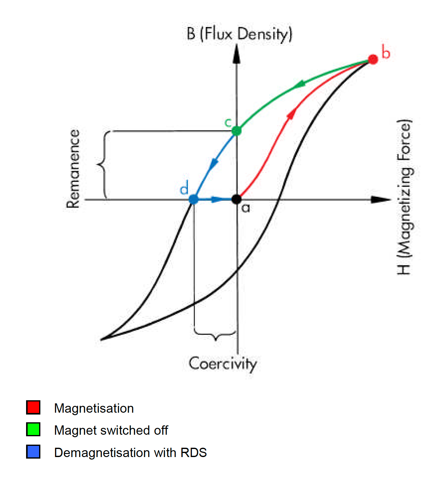
Figure 3: Hysteresis of soft magnetic mild steel
RDS cannot be applied to hard magnetic material because the negative magnetic field causes all the ions to adopt a reverse alignment instead of returning to a random state.
DDS (Downcycle Degauss System)
DDS reduces the residual magnetism in hard quality steel by applying a series of polarity changes in a magnetic field of ever decreasing amplitude as shown below in Figure 4:
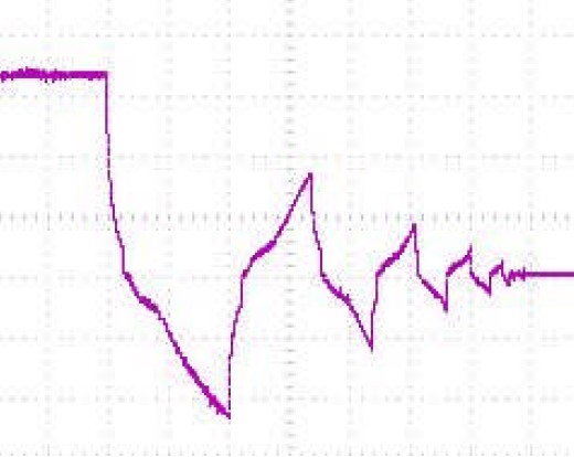
Figure 4: Typical magnet current behaviour during DDS demagnetisation
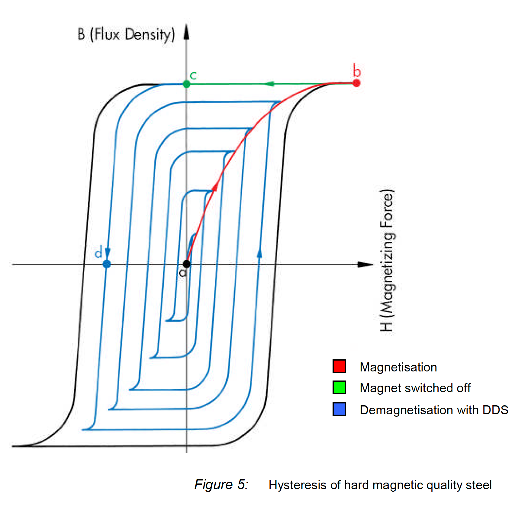
With this approach the magnetic ions are effectively ‘shaken’ into a random state, reducing the residual magnetism to around 2 mT.
Figure 5: shows the resulting hysteresis:
FE method
Steel mills and logistics companies handle huge quantities of hot strip coils every day. This is done either in internal transport as semi-finished products or as sales products. TRUNINGER coil magnet systems enable fast and safe handling as well as loading and unloading of all possible means of transport, e.g. trucks, rail cars, or ships.
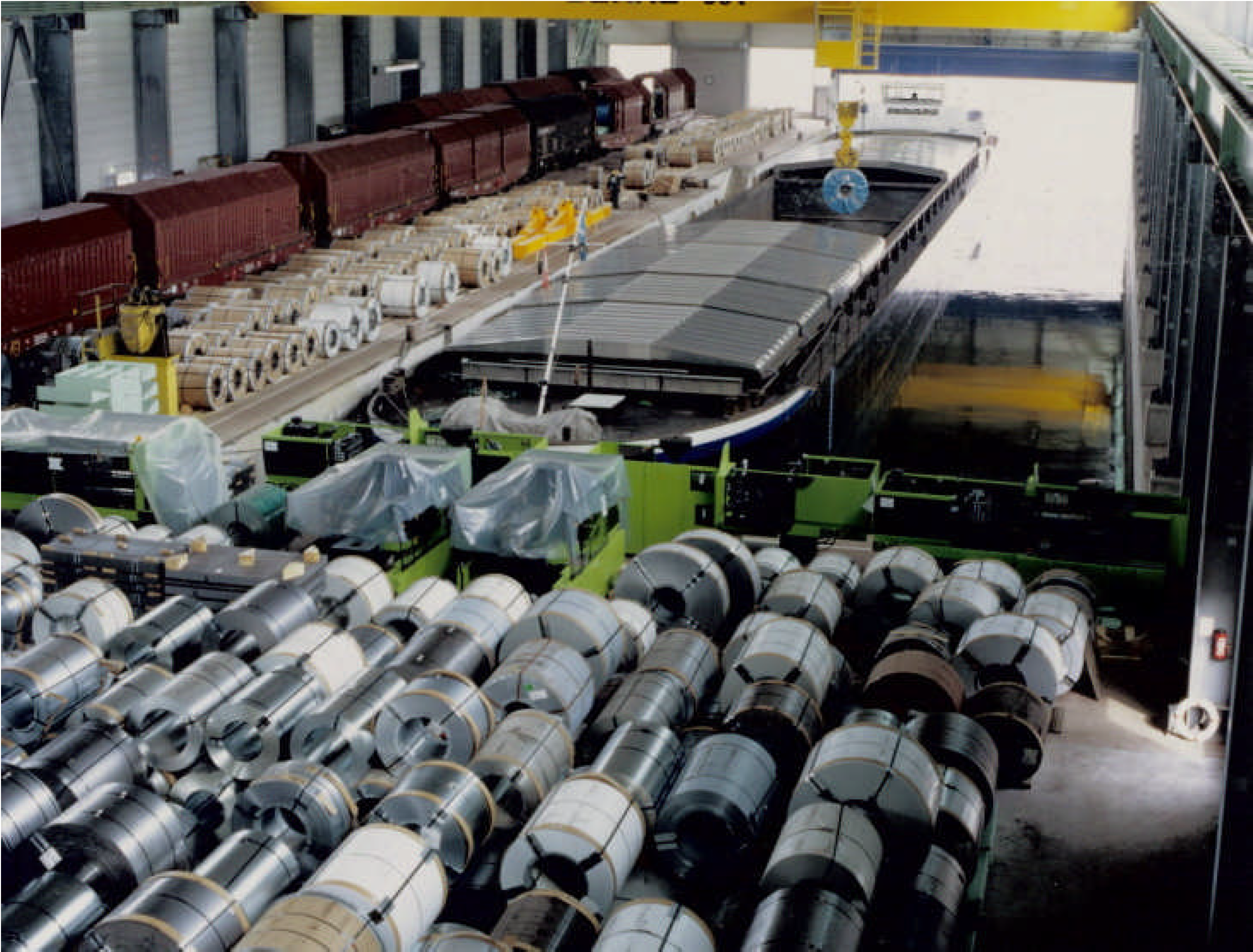
Figure 1: Magnetic coil transport in ships and railroad wagons
In contrast to cold-rolled coils, hot-rolled coils are not smoothly wound after cooling since the individual layers contract. This results in air gaps between the sheet layers. The larger the air gap or the sum of the air gaps in the coil, the more it impairs the magnet's lifting force (see Fig. 3). For safety reasons, this loss of lifting force must be compensated.
TRUNINGER has developed coil magnets with a specially aligned magnetic field for deep penetration into the hot strip coils especially for these applications. Magnet dimensioning and magnet design at TRUNINGER use the computer-aided so-called FE method. The finite element simulation helps optimize existing magnet designs as well as to develop new, customer-specific magnet solutions. In addition, lifting force, magnetic penetration depth, and air gap compatibility can be simulated in the computer. It guarantees the smooth implementation of customer specifications from theory to practice.
Advantages
| Your benefits
|
Transport of two Tube Bundles
Handling one or two tube bundles simultaneously
The production speed of welded tubes depends very much on the thickness of the tube wall. Thin-walled tubes are produced much faster than thick-walled tubes. In order to be able to handle all products of a tube production line using just one magnet crane, bundles of thinwalled tubes need to be moved around at a sufficiently fast rate.
This is achieved by picking up one heavy or two lighter tube bundles. By doing this not only does the volume handled get adapted to the production speed, but optimum utilisation of the crane capacity is also achieved.
The magnets can either be placed in line for transporting single bundles or offset side by side for carrying double bundles. The lateral movement of the magnets can be automatically set in 7 freely programmable positions and thus adapted to the bundle size
Example applications
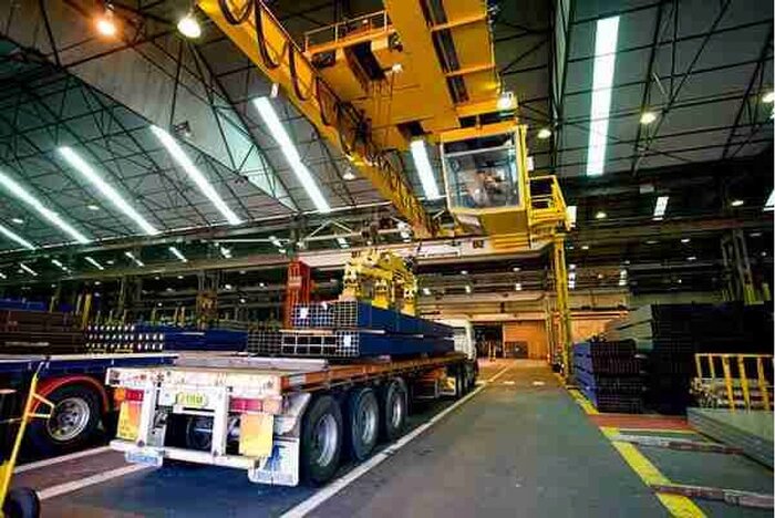
Figure 1: Carrying double bundles of thin-walled tubes for efficient loading of trucks at OneSteel in Australia.
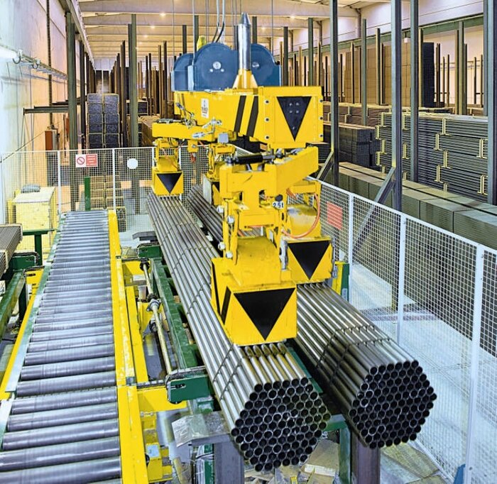
Figure 2: Clearing the end of a tube production line at Aratubo in Spain
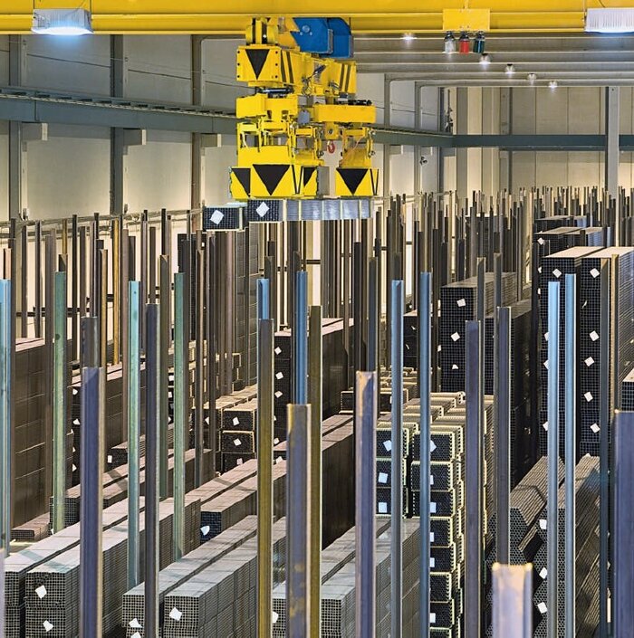
Figure 3: Automated warehouse with maximum storage density (no aisles between the racks, stacks up to 6 metres high) at Aratubo in Spain
Vertical Plate Storage
Oblique is possible
Magnetic systems for vertical plate storage are a trend-setting development from TRUNINGER. For highly varied storage systems, they represent a compact alternative to the horizontal storage of plates on the floor: With a single unit, plates can be picked up horizontally or vertically as well as deposited again in the required position.
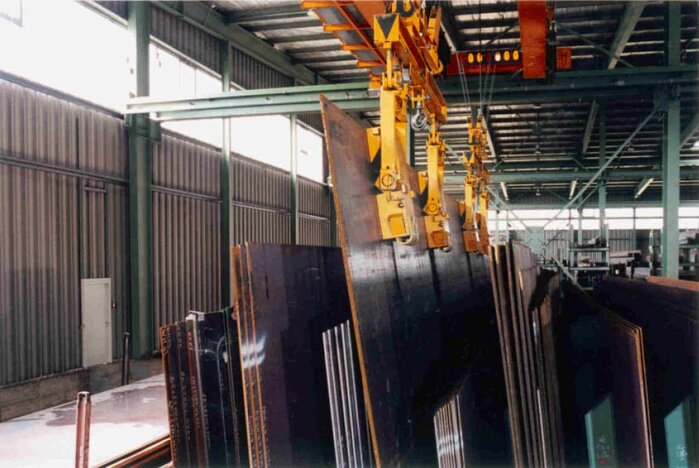
Figure 1: High storage density with vertical plate storage
High storage density—short transport distances
The vertical storage of the plates massively increases the storage density, shortens the access time and enables direct commissioning of a wide variety of sheet metal. grades from the storage location to the truck or to further processing without additional transport equipment.
Advantages
- The distances between the individual material racks are extremely small thanks to the flat magnet design.
- There is no need to restack the material because storage is sorted by type.
- Commissioning of the individual plates is simple and quick.
Your benefits
- Store significantly more material in the same amount of space.
- Results in shorter transport distances on an average.
- Time savings in plate commissioning.
- One system for all sheet metails according to the motto "One size fits all!".
- Vertical and horizontal storage can be combined with the same system.
Born out of experience: the technology
By using special tilting devices, it is possible to pick up and deposit plates both horizontally as well as vertically. When in basic position, the magnets are suspended vertically in the tilting device. In this position, the crane operator moves the magnets between the stacks of the vertical plate storage system to pick up the plates (see Fig. 1).
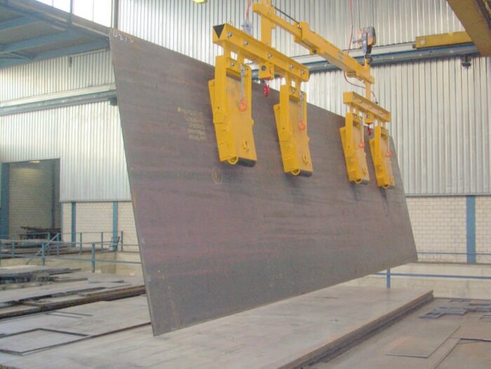
Figure 2: Picking up a horizontally lying load
To lift a horizontal load, the magnets must be placed on the load. A rolling mechanism automatically rotates the magnets into a lying horizontal position when they are placed on a horizontal plate. To bring the plate into a vertical position, the magnets must be placed on the outer edge of the plate (see Figure 2).
Figure 3: Magnets locked in horizontal position
For the exclusive transport of plates in a horizontal position, e.g. when clearing a firing table, the magnets can be locked in the horizontal position using the chains provided (see Figure 3). This simplifies the handling of the magnets considerably and saves time. Accordingly, these chains must be unhooked again for transporting plates in the vertical position.
Depending on the crane configuration, different crossbeam designs result in the widest possible range of applications for magnet systems for heavy plate transport in horizontal and vertical positions. For very broad plates, oblique storage is often the only alternative for transport on trucks or railroad wagons (see Fig. 4).
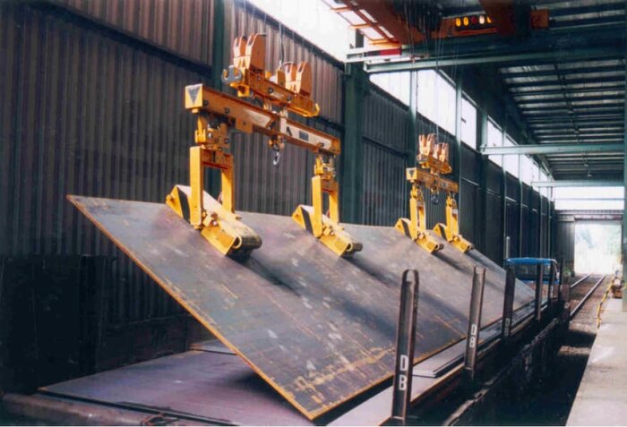
Figure 4: Wagon unloading, pickup of broad heavy plate
Even special formed workpieces, e.g. stiffened ship's sides, can be transported to the assembly site without any problems with a vertical plate system from TRUNINGER.
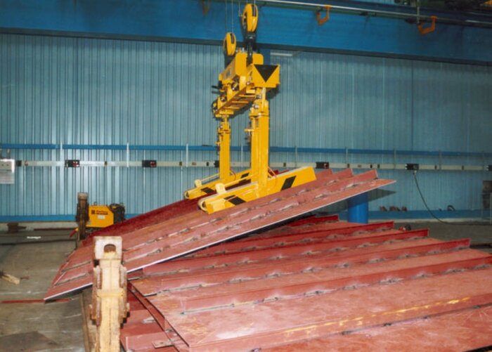
Figure 5: Transport of ship sides at a shipyard
Redundant System Design
Why redundant system design
Electrical controls are built using a whole bunch of sub-systems which all have a certain potential of failure. To provide safety of the system in case of a single sub-system failure, safety relevant sub-systems are built redundant (double). The two sub-systems working on the same task are cross-checked to make sure, that both systems work fine. Two redundant systems do not add much to safety, if failure of one system is not detected.
Therefore, redundancy, cross-check and safety relevance are part of safety class 3 design concept also referred to in international standardization document DIN-EN 954-1.
Standard redundant components
The concept of redundancy is a central feature built-in Truninger magnet system controls. All safety relevant sub-systems are built according to the safety class 3 standard. The following subsystems are covered:
- Two power sources, mains and backup battery. Backup battery capacity is designed to maintain safe operation for at least 20 minutes.
- Two current sensors and two associated cross-checked signal processing units. Failure of one sensor will be detected and trigger a switch over to battery operation and system lock (magnet can be switched Off but no more On).
- Two power switches, one dedicated to mains power, one dedicated to battery power. Failure of power electronics IGBT (transistors) will cause the second current loop to take over and also lock the magnet system. Both power switches are checked in every load cycle.
- Two controllers built in different hard and software. Any failure of the SmartPickTM main controller will hand over the control task to the slave controller SafePickTM. Also here, both controllers are checked continuously by each other.
- Two low voltage power sources. Each of the two controllers is equipped with individual low voltage power sources. Such power sources are cross-checked and both are battery backupped.
Optional redundant components
Most often, the power lines from the controller to the magnet are considered safe and therefore not built redundant. However, in some harsh environments, cables and cable drums can not be considered safe.
If required, total redundancy can be achieved building up two independent electric power circuits to the magnet. Two independent cables, two cable drums, two electric coils in the magnet and two power supplies PowerPickTM build up such independent electric power circuits. Even a short cut at any location of one circuit will not stop this system from operating.
Example: Below is a typical gantry crane installation with an integrated, total redundancy coil magnet system:
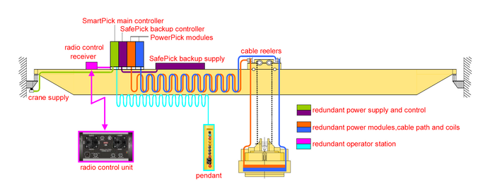
Figure 1: Magnet system with total redundancy electrical system
The redundant components are:
- Two PowerPickTM modules.
- Two sets of flat cables.
- Two cable reelers.
- Two independent coils inside the magnet.
This arrangement forms two completely independent end-to-end power circuits which guarantees safety of the load even in the event of partial or complete failure of one circuit.
Also a redundant operator control sub-system ensures that the magnets may be operated from a backup pendant if the radio control unit or radio receiver are faulty.
Coil Rotator
Easy rotation of large loads
Further processing on slit coils often requires them to be rotated from the horizontal into the vertical position or vice versa.
TRUNINGER has developed magnetic coil rotators for this purpose. Coil rotators offer:
- Easy transport of coils to and from store
- Direct transfer of coils from store to mandrel of processing machine
A coil rotator is an alternative to chains and slings. The magnet grips the slit coil gently on its surface. Maximum contact area guaranteeing the required adhesive force for rotating the coil safely and protects the coil from damage.
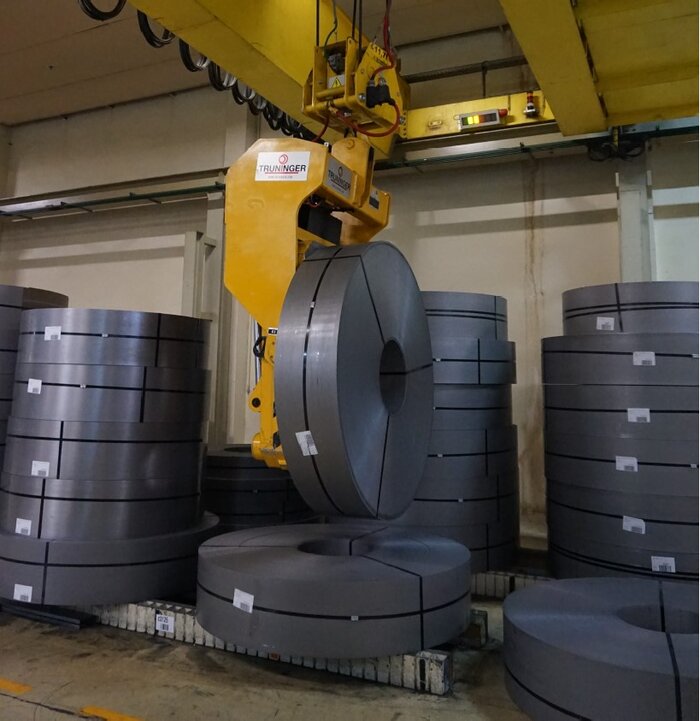
Figure 1: 8t coil rotator in position – winding axis horizontal
The magnet is designed in such a way that the coil eye remains unobstructed. The slit coil can thus be pushed straight onto a decoiler without any additional step in the working process.
Advantages
| Your benefits
|
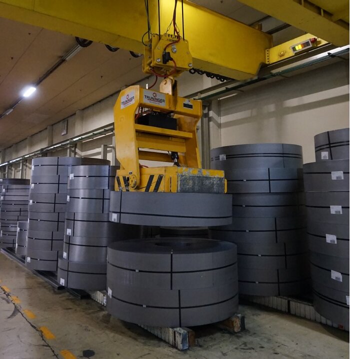
Figure 2: 8t coil rotator in position, winding axis vertical
QuickChange™ System
Flexibility increases profitability
The QuickChange™ system enables a single crane to use a range of different magnet spreader beams. Controlled remotely by the operator, the lower spreader beams are linked both mechanically and electrically to the upper spreader beams permanently attached to the crane. Product-specific magnet spreader beams are needed for different applications, for instance, in the prefabrication hall of a large sectional steel service centre.
For moving the individual sections from the warehouse to the saw, sandblaster, processing centre or dispatch area, especially narrow magnets are used, enabling the cranes to work even in tall narrow aisles between the stored material. This enables the user to achieve maximum storage density.
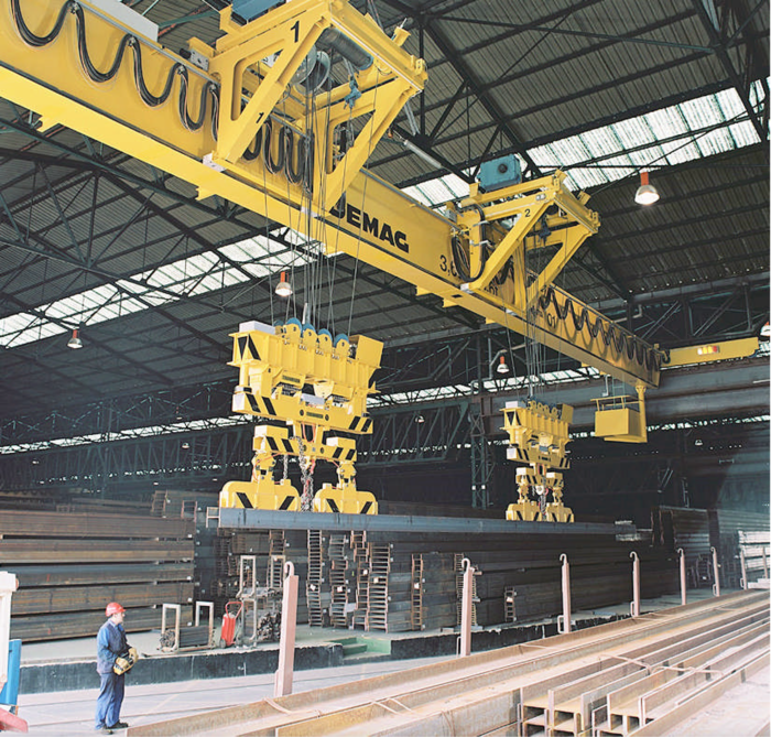
Figure 1: QuickChange™ system with lower spreader beams for handling individual sections in the prefabrication area
Switching spreader beams faster and with added ease
The sections are usually delivered by train or ship in packs weighing up to 8,000kg. To keep costs down, these packs of sections need to be unloaded and moved to their respective storage locations as quickly as possible.
Large magnets with a deep magnetic field are used to move the packs around efficiently and safely. These magnets are attached to two further lower spreader beams. To change magnets, first the two lower spreader beams for individual sections are lowered onto their spreader beam stands and decoupled.

Figure 2: Automatic decoupling of the lower spreader beams for individual sections
The two lower spreader beams for bundled section packs are then attached. Using a remote control unit or suspended keyboard, the crane operator is able to change the spreader beams within a matter of seconds, without having to bother with any hooks or plugs.
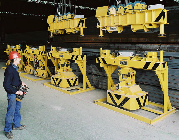
Figure 3: Quick coupling up of the section pack magnets for fast and efficient unloading of trains and ships
Residual Magnetism
Why demagnetisation of the load can be critical
In material handling applications where the steel has to pass though automated processing lines, residual magnetism in the load can cause serious problems. The load may ‘stick’ to machine parts as it travels through the production line or it may attract other small pieces of steel (washers, bolts, swarf etc).
In these situations efficient demagnetisation of the load is essential. SmartPick offers configurable demagnetisation for eliminating a maximum amount of residual magnetism in minimum time.
What happens when steel becomes magnetised?
Ferromagnetic materials such as such as mild or quality steel which have never been subjected to a magnetic field are made up of randomly ordered magnetic ions as represented below in Figure 1. Steel, when in this state, has no magnetic effect on its surroundings (see point a in Figure 3:).
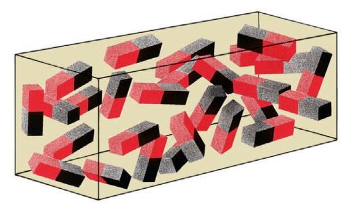
Figure 1: Ions positioned at random (material demagnetised)
When a positive magnetic field is applied, the magnetic ions start to fall into alignment. The more powerful the magnetic field, the more tightly the ions are aligned. If all of the ions are aligned as shown in Figure 2:, the material is said to be magnetically saturated (Point b in Figure 3:). For steel the magnetic saturation is equal to 2.4 Tesla.
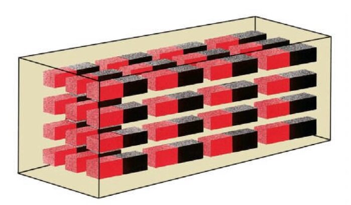
Figure 2: All ions aligned (material magnetically saturated)
However, when the external magnetic field is removed, the ions do not return to their random state. This leaves some residual magnetism in the material, an effect known as remanence (Point c in Figure 3).
This residual magnetism has to be removed by some external means. The actual method applied depends mainly on the magnetic properties of the material. Material such as mild steel loses its magnetism quickly and is said to be ’soft magnetic’. Quality steel on the other hand, loses its magnetism very slowly and is therefore said to be ‘hard magnetic’.
RDS (Reverse Degauss System)
RDS demagnetisation eliminates residual magnetism from mild steel. Applying a negative magnetic field causes the magnetic ions to gradually adopt a random alignment. When the opposing field is turned off (Point d in Figure 3:), the ions are randomly aligned, thus eliminating the residual magnetism.
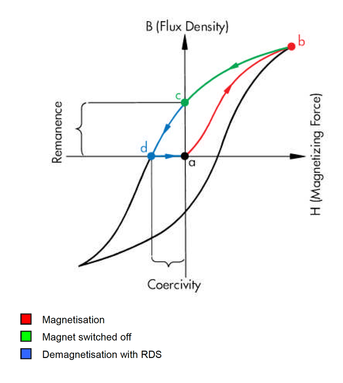
Figure 3: Hysteresis of soft magnetic mild steel
RDS cannot be applied to hard magnetic material because the negative magnetic field causes all the ions to adopt a reverse alignment instead of returning to a random state.
DDS (Downcycle Degauss System)
DDS reduces the residual magnetism in hard quality steel by applying a series of polarity changes in a magnetic field of ever decreasing amplitude as shown below in Figure 4:
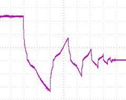
Figure 4: Typical magnet current behaviour during DDS demagnetisation
With this approach the magnetic ions are effectively ‘shaken’ into a random state, reducing the residual magnetism to around 2 mT.
Figure 5: shows the resulting hysteresis:
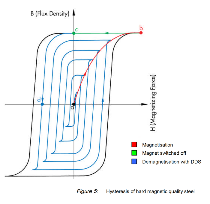
Retractable Pole Anchor
Time is money
Economical and precise picking is extremely important for the steel trade. The TRUNINGER SmartPickTM magnet control system enables us to meet demanding client-specific requirements for efficient and reliable material picking.
Variable grippers
You need the right approach to have a good grip on things! This naturally applies to magnetic grippers, too. At TRUNINGER the spreader beams and magnets are developed and built to suit each specific task. The model particularly well suited to the task of effective, precise and fast picking is the…
Retractable pole anchor
Developed by TRUNINGER – as simple as it is ingenious! With a retractable anchor integrated into the magnetic pole, the pole surface size can be automatically adapted to the load to be lifted. With the retractable anchor extended, individual bars or small quantities can be picked with ease.
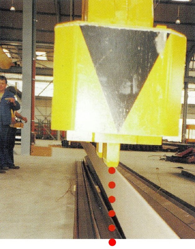
Figure 1: Extended anchor lifts a single section
For large loads or bundles the anchor retracts automatically as the magnet pole is set down onto the surface of the material to be lifted. The whole surface area of the magnet pole is thus then available, ensuring safe, reliable transport.
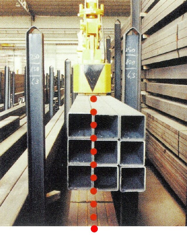
Figure 2: Safely picking a bundle using the complete pole surface
Slab Turner
Gentle turning over of slabs
Ongoing development in continuous casting technology has led to nearly all grades of steel now being cast in a single strand. Due to the diverse range of steel grades and the different manufacturing methods the strand’s surface needs to be treated for the next stage in the process. The blank gets further processed, for instance, by flame scarfing or high-pressure grinding. For deburring and grinding the slabs need to be turned over.
Magnet lifting systems from TRUNINGER are an alternative to stationary, hydraulic slab turning devices that require a lot of maintenance. Magnet spreader beams for use in slab turning applications have an especially robust design, making them suitable for cold as well as hot material.
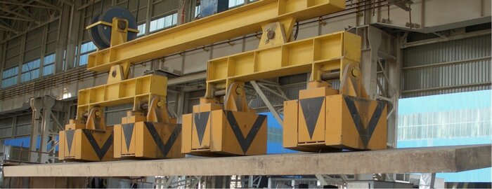
Figure 1: Slab turning magnets taking a slab from a stack for further processing
The advantages of using a magnet system are obvious
| This results in major benefits
|
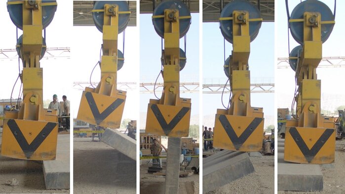
Figure 2: Turning of a slab using magnets
TRUNINGER design features
TRUNINGER designs and manufactures special magnet systems for handling all kinds of heavy loads.
- Robust spreader beam design and durable magnet construction are built-in features of the magnetic systems designed specifically for slab turning applications.
- The magnet beams’ design is adapted to the relevant material specifications. Both individual magnets (see figure 2) and simple fixed beams with multiple magnets are used.
- Specially developed magnets with temperature-resistant coils guarantee a long service life under rugged conditions.
- The magnets are also fitted with reflection plates to protect the coils against radiated heat.
- The magnet control system is fitted with a back-up battery as standard and automatically switches from mains to back-up power in the event of mains failure.
- The entire magnet system can be designed with built-in redundancy, i.e. from the magnet controller via the power supply, right through to the magnet coils, the system incorporates fully redundant components.
Modular Design
Why modularity?
The electrical components of Truninger magnet systems are composed of a number of discrete, separately orderable modules. This multi-level modularity offers a number of benefits:
- It allows mass production of modules based on tried and tested technology
- All cabinets have the same dimensions regardless of function
- All board/component level spares are available from stock
- Many operational features are software configurable
- Ease of integration and maintenance
- Scalability: easy to add extra magnet groups if required
Electrical component hierarchy
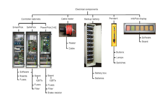
Figure 1: Hierarchy of electrical components
Maximum/minimum configuration
Modular cabinet design means the controller can be adapted to suit a wide range of applications. Figure 2 below shows a maximum configuration with battery backup and eight magnet groups:
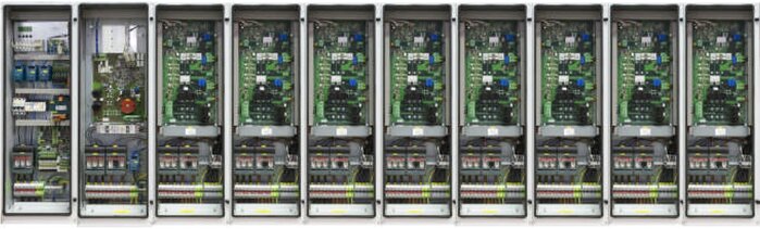
Figure 2: SmartPickTM maximum configuration
Only two cabinets are required for a minimum configuration supporting a single magnet with no battery backup (cf. Figure 3). This arrangement would be suitable for a scrap magnet application for example.
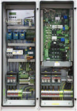
Figure 3: SmartPickTM minimum configuration
Remote Helpline
Remote troubleshooting: quick and easy with cell phone link
When your magnet system develops a fault and technical support is not available locally you can use your Bluetooth-enabled cell phone to establish a direct ’helpline’ link between your system and a server located at the Truninger support centre. Figure 1 below gives an overview of how the link is built up:
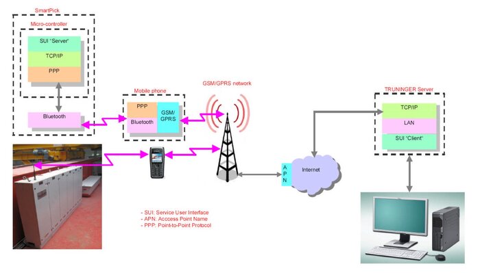
Figure 1: Architecture of the remote helpline link
The link is setup in two easy steps:
- To initiate the remote helpline setup you have only to establish a Bluetooth connection between your cell phone and the SmartPick unit of your faulty magnet system.
- The SmartPick unit then automatically makes a call, via your cell phone, to the Truninger server using its locally stored subscriber number and APN (Access Point Name).
Once the link with the server is established, a service technician can then ’log in’ to your system to begin fault analysis and quickly determine the cause of the breakdown.
Redundant Magnet System
1. What is redundancy?
Electrical controls are built using a whole bunch of sub-systems each having a certain potential of failure. To provide safety of the system in case of a single sub-system failure, safety relevant subsystems are built double, generally referred to be “redundant”. Two sub-systems work on the same task and also cross-check each other to make sure, both systems work fine. Two redundant systems do not add much to safety, if failure of one system is not detected. Therefore, redundancy, cross-check and safety relevance are core elements of safety class 3 design concept also referred to in international standardization document DIN-EN 954-1.
2. Standard redundant components
The concept of redundancy is a central feature built-in Truninger magnet controller SmartPickTM. All safety relevant sub-systems are duplicated according to the safety class 3 standard.
The following sub-systems are covered:
- Two power sources- mains and backup battery
Backup battery capacity is designed to maintain safe operation for at least 20 minutes in case of mains power failure. - Two current sensors—two associated cross-checked signal processing units
Failure of one sensor will be detected and triggers a switch over to battery operation and system lock (magnet can be switched OFF but no more ON). - Two power drives—AC/DC & DC/DC
One drive dedicated to mains power AC/DC and one drive dedicated to battery power DC/DC. Failure of power electronics in any drive such as IGBT transistors will cause the second drive to take over and also lock the magnet system. - Two controllers built in different hard and software
Any failure of the SmartPickTM main controller will hand over the control task to the slave controller SafePickTM. - Two low voltage power sources
Each of the two controllers is equipped with individual low voltage power sources. Such power sources are continuously cross-checked and both are battery backed.
Optional redundant electric circuits
Most often, the power lines from the controller to the magnet are considered safe and therefore not built redundant. However, in some harsh environments, cables and cable drums can not be considered safe.
If required, two independent electric power circuits for one single magnet can be realised. Two cables, two cable drums, two electric coils in the magnet and two power modules PowerPickTM build up such independent electric power circuits. Even a short cut at any location of one circuit will not stop this system from operating.
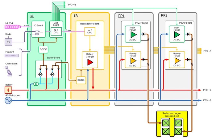
Figure 1: Redundant Magnet Controller SmartPickTM
| SP | Module SmartPick (SP), Nr. 1 CPU controlling AC/DC drive, signal inputs, redundant low power supply |
| SA | Module SafePick (SA), Nr. 2 CPU controlling DC/DC drive, battery charger, battery supervision / maintenance (automatic capacity test) |
| PP 1 & 2 | Module PowerPick (PP), generates safe DC Power for magnet uniting mains- and battery power drive |
| InfoPick | Module InfoPick, graphic display informing the operator and staff on the ground visually and acoustically about the state of magnet system |
| Operation | Two operation units can be connected to SP, if one of operation unit fails, another unit can be used as backup |
| Magnet Coil | Redundant magnet with double coil each connected to one PP module, this results in safe power supply keeping up sufficient magnet force in case of any power circuit Coil failure |
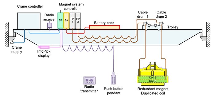
Figure 2: Magnet system on overhead crane
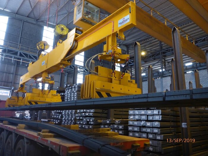
Figure 3: Redundant magnet system for bar bundles
Black Box / Event Log
A vital troubleshooting tool to minimise your system down time
Similar to the black box recorder of a modern aircraft, all major system events, faults and most operator actions are recorded in an event log. Up to 4,500 individual events can be stored in SmartPick’s non-volatile memory; this corresponds to approximately 200 load cycles of the magnet system.
In case of a breakdown, the events can be traced in detail making the event log a most valuable tool for troubleshooting . Detailed understanding of a problem allows to trigger the appropriate corrective action. Quite often, problems can be solved by telephone or email, saving a lot of time and cost as no specialist needs to rush on site. .
The event log can be accessed by laptop using SmartPickTM’s built-in BlueTooth module, nobody needs to climb up the crane (see figure 1 bellow).
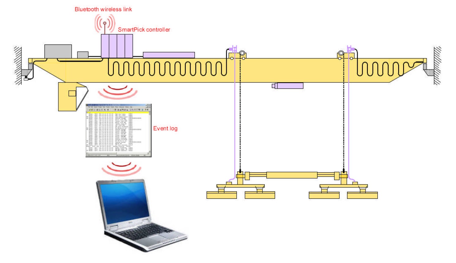
Figure 1: Accessing the event log using BlueTooth interface
The event log can be stored in a readable text file and e-mailed to a Truninger support centre for rapid analysis by a system specialist.
Inside the event log
All events logged have a unique event number and carry a date/time stamp; it is therefore possible to determine, to the nearest second, exactly when a particular event occurred. Events cover the following types of information:
- Magnet on/off cycles
- Magnet current and battery voltage
- Use of special features such as Partial Drop (order picking)
- Mains failures and battery switches
- Magnet lifting force selected during material handling operations
- Magnet and environment temperature
- State of crane interface signals
- System information: controller restarts, software versions, system id
- Changes to configuration data
Example: weak battery
The batteries play a critical role in the operational safety of a magnet system. Battery capacity is therefore tested every time the magnets are switched on and when insufficient, power on is aborted.
The following extract of the event log shows an attempt to switch on the magnets when battery test fails due to high voltage drop. Note that the most recent events appear first (so read bottom up for chronological order):
Event: 3398: 214 14:29:48 05.10 RB:chrg enabled 00000
Event: 3397: 145 14:29:44 05.10 Hoist lock OFF 00001
Event: 3396: 147 14:29:44 05.10 Travel lock OFF 00001
** Event: 3395: 012 14:29:20 05.10 RB:Bat test fail 01999
Event: 3394: 206 14:29:20 05.10 RB:bat voltage 00101
Event: 3393: 144 14:29:18 05.10 Hoist lock ON 00001
Event: 3392: 146 14:29:18 05.10 Travel lock ON 00001
Event: 3391: 213 14:29:18 05.10 RB:chrg disabled 00000
Event: 3390: 128 14:29:18 05.10 CB:VG ON 01000
The key events we see here are the following:
- Operator gives command to switch on a magnet (event 3390)
- Measured battery voltage just before battery test is 101 Volts (event 3394)
- Battery test fails because of excessive battery voltage drop (event 3395 data ‘999’)
Auto-positioning of Magnets
The difficulty of manual positioning
When using an active telescope to work with different lengths of material you will often need to adjust the spacing between your magnets. In the case of long flexible material such as rebars for example (see Figure 1:), precise positioning can be critical if you want to avoid excessive bending of the load. This can be a safety issue.
The traditional motor control arrangement requires you to operate a 3-position spring-loaded switch (left-stop-right) to start the magnets moving in the desired direction. You must then release the switch (motor stop) once the required position is reached. The entire procedure is manual and correct positioning of the magnets relies on visual judgement alone which can be problematic if you are at some distance from the working zone or if visibility is impaired.
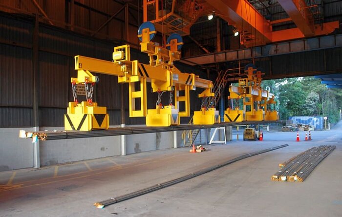
Figure 1: Active telescope transporting different lengths of rebars.
Precision and time-saving with auto positioning
With the Truninger auto-positioning feature it is possible to move the magnets to any one of up to eight pre-defined positions. These positions, pre-defined according to the different lengths of material you need to handle, are set up initially by a technician during commissioning of your system but may be re-programmed at any time.
Two different switch options are possible for controlling the auto-positioning:
- The simpler option uses the existing 3-position motor switch. With this arrangement the switch is turned in the desired direction of movement and held in position. The magnets will start to move in the selected direction and stop automatically when the next programmed position is reached. Movement of the magnets can be interrupted at any time simply by releasing the switch.
- A more flexible solution is to install an 8-position rotary switch allowing the target position (0-7) to be pre-selected. The magnets will then be set in motion by activating a springloaded 2-position switch and stop automatically when the pre-selected position is reached. Again, the magnets can be stopped at any time by releasing the 2-position switch.
When auto-positioning is activated the InfoPick display changes as shown below in Figure 2:
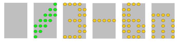
Figure 2: InfoPick display during movement of magnets
The rotating green element indicates movement of the magnets; the yellow elements display the programmed text corresponding to the target position (3-6m in this example).
When the magnets stop at the target position the InfoPick display changes as follows:
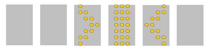
Figure 3: InfoPick display when magnets reach target position
This remains for 3 seconds after which the InfoPick display reverts to the state it was in prior to activation of the auto-positioning.
Safety gripper
Special devices
Our extensive experience of different applications as a magnet system manufacturer allows us to offer solutions for special projects as well as standard applications (see ‘Custom spreader beams’ document). One such solution created in response to customer-specific demands is our safety gripper.
TRUNINGER magnet systems are equipped with every conceivable mechanical and electrical/electronic safety feature as standard in order to achieve maximum safety levels when handling material magnetically. A load lifted with magnets could actually be secured to the spreader beam with chains.
However, this would be very time-consuming and potentially dangerous as workers would have to approach the suspended load to attach the chains. This is why TRUNINGER developed the safety gripper.
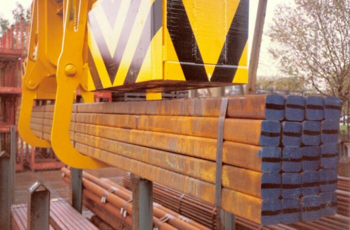
Figure 1: Safety gripper with secured load
An open/close mechanism remotely controls the safety gripper. For handling reasons the safety gripper should be only slightly wider than the magnets as any extra width would have a negative impact on storage density, speed of access to material, deadweight, operability, etc. The safety gripper is therefore ideally suited for use with long products.
As the magnets grip and lift the material, the safety gripper is in the open position. Once the load has been lifted, the gripper is closed. The load then continues to be carried magnetically. The safety gripper is only used in an extreme emergency, i.e. in the event of the magnets dropping the load.
If necessary, the gripper can also be coupled to the crane’s operation, i.e. it can be made impossible for the crane to move if the safety gripper is not fully open or closed.
Easy operation
Simplicity, safety, flexibility
Basic operation of the magnets is reduced to a simple ON/OFF action from the operator station. To minimise the risk of accidental power off, switching off the magnets is always a two-handed operation requiring the simultaneous pressing of two separate buttons: OFF and ENABLE (see controls 2 & 3 in Figure 1:), located on opposite sides of the operator station.
In multiple-magnet systems you may choose to switch on or off all or only selected magnet groups (see group buttons 4 in Figure 1).
Magnet and crane controls in a single unit
In the case of overhead cranes operated from the factory floor the magnet and crane controls will generally be integrated into a single radio remote control unit similar to the one shown in Figure 1:
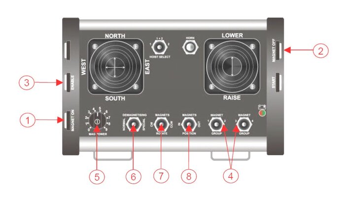
Figure 1: Typical radio remote control unit for crane and magnets
Automatic handling of crane interface functions
Automatic handling of crane interface functions To ensure safe, seamless interworking with the crane all basic crane control signals and interlocks are handled automatically by the SmartPickTM unit. The following crane interlock signals are provided as standard and prevent or restrict movement of the crane if the magnets are not in the appropriate state:
- Hoist Lock: prevents activation of the crane hoist if the magnets have not reached a stable power setting. During power-up the first stable power state corresponds to the preselected Partial Load level. When the operator issues the power-off command, the crane hoist remains locked until the magnet current has reached zero.
- Travel Lock: the crane travel is immobilised or restricted to slow speed until the magnets have switched to full lifting force (Full Load).
As an additional safety feature, if the crane provides a LOAD SUSPENDED signal SmartPickTM will ignore a magnet OFF command issued while a load is still suspended.
Working with reduced power
It is not always necessary or desirable to use the full lifting force of the magnets. For example when you want to lift small quantities of a material or selectively drop certain items such as plates, you will need to reduce the magnet power. There are two ways of controlling magnet lifting force:
- Pressing the ON and ENABLE buttons together (cf. 1 and 3 in Figure 1) will cause the magnets to switch to the pre-selected partial load setting. The magnet lifting force can then be further adjusted by turning the rotary selector switch (cf. control 5 in Figure 1).
- Once the magnets are in partial load, the lifting force may be gradually reduced by keeping the ON button pressed. This operation (Partial Drop) is convenient for plate handling when you need to drop only the bottom few plates.
Time saving advantage
By using a TRUNINGER magnet system you save not only space, but lots of time as well.
Magnets, when properly operated, allow you to:
- Approach the load quickly and reliably
- Grip the load securely
- Lift the load from its storage location in a few seconds
Magnet systems also enable everything in the warehouse to be tightly packed, which results in shorter average crane travel distances and therefore saved time.
Handling more material in small space
Where automatic storage of long products is not economical, storing material in stacking cradles can be a useful alternative. In situations where small volumes or small quantities of material are stored and transported, what is needed is often just a lifting system which allows:
- Easy access
- Low space requirement
- Simple operation
Using a stacking cradle system it is possible to store large quantities of material in a very compact space. Such a storage system is the ideal, flexible solution for space-saving, safe storage of long and/or flat material as well as products in large quantities.
Figure 1: View of a typical stacking cradle storage system
Magnet Lifting System with Cradle Carriers
Cradle carriers fixed on the magnet beam allow several operations with the same system:
- Rapid loading of the bundle into the stacking cradle
- Simple mechanical re-stacking of cradles
- Precise order picking of individual items using the magnets
By using the cradle carrier system to alter the stacking order, material lower down is always accessible. There is no longer any need for any manual rearranging.
The magnet system’s cradle carriers are located between the two magnets of a magnet group. The lugs are swivelled out by a motor.
Figure 2: Mechanical restacking of a cradle
Before order picking with the magnets the motor swivels the lugs back. The entire cradle carrier is no wider than the magnets. Long material can therefore be picked without any obstruction.
Figure 3: Order picking from the stacking cradle
For structural reasons a different cradle carrier design is needed for wide or flat loads. Here the carrier lugs no longer get swivelled out. Instead a motor rotates the entire carrier mechanism.
Figure 4: Carrying cradles using rotatable carrier mechanisms
Upright storage is possible
One very interesting TRUNINGER development is the use of magnet systems for vertical plate storage. In warehouses with a very diverse range of material, storing plates this way is a space-saving alternative to horizontal floor storage. Using a single system it is possible to pick up or set down the plates in either the horizontal or vertical positions.
Figure 1: High density plate storage in upright racks
Very compact storage—short travel distances
Storing plates vertically greatly increases the storage density, shortens access times and enables direct picking from the storage area onto the lorry or into the processing area—and all without the need to use any other lifting devices.
Advantages
| Your benefit
|
Technology born from experience
Tilting magnets allow plates to be picked/transported in the horizontal or vertical positions. The magnets are designed to hang vertically. In this position it is possible to move the crane into a tightly packed vertical plate storage area to pick a single plate. (see figure 1).
Figure 2: Picking up a load from a horizontal position
It is also possible to pick up a plate horizontally and pivot into the vertical position during lifting. A roll-off mechanism ensures that the magnets pivot into the horizontal position as they are being set down. In order to lift the plate into the vertical position, the magnets must be placed off-centre towards one side of the plate (see figure 2).
Figure 3: Magnets locked in horizontal position
For pure horizontal operation, the magnets can be kept horizontally using the provided mechanical locking mechanism. (see figure 3). This speeds up and eases handling. For vertical lifting the mechanical locking mechanism must be disengaged.
Depending on the crane configuration, different spreader beam designs offer many different ways of transporting plates in the horizontal or vertical positions. For very wide plates oblique storage is often the only option for transport on lorries or railway wagons (see figure 4).
Figure 4: Unloading a wagon. Picking up a wide steel plate
Specially shaped components, such as reinforced ship wall elements, can also be transported easily to the assembly area using a TRUNINGER vertical plate lifting system.
Figure 5: Carrying hull elements in a shipyard
Time saving advantage
By using a TRUNINGER magnet system you save not only space, but lots of time as well.
Magnets, when properly operated, allow you to:
- Approach the load quickly and reliably
- Grip the load securely
- Lift the load from its storage location in a few seconds
Magnet systems also enable everything in the warehouse to be tightly packed, which results in shorter average crane travel distances and therefore saved time.
Handling more material in small space
Where automatic storage of long products is not economical, storing material in stacking cradles can be a useful alternative. In situations where small volumes or small quantities of material are stored and transported, what is needed is often just a lifting system which allows:
- Easy access
- Low space requirement
- Simple operation
Using a stacking cradle system it is possible to store large quantities of material in a very compact space. Such a storage system is the ideal, flexible solution for space-saving, safe storage of long and/or flat material as well as products in large quantities.
Figure 1: View of a typical stacking cradle storage system
Magnet Lifting System with Cradle Carriers
Cradle carriers fixed on the magnet beam allow several operations with the same system:
- Rapid loading of the bundle into the stacking cradle
- Simple mechanical re-stacking of cradles
- Precise order picking of individual items using the magnets
By using the cradle carrier system to alter the stacking order, material lower down is always accessible. There is no longer any need for any manual rearranging.
The magnet system’s cradle carriers are located between the two magnets of a magnet group. The lugs are swivelled out by a motor.
Figure 2: Mechanical restacking of a cradle
Before order picking with the magnets the motor swivels the lugs back. The entire cradle carrier is no wider than the magnets. Long material can therefore be picked without any obstruction.
Figure 3: Order picking from the stacking cradle
For structural reasons a different cradle carrier design is needed for wide or flat loads. Here the carrier lugs no longer get swivelled out. Instead a motor rotates the entire carrier mechanism.
Figure 4: Carrying cradles using rotatable carrier mechanisms
Your benefits at one glance
|
|